|
A crucial part of the Arduino algorithm involves calibrating the Arduino to detect a number of improper positions and alert the user accordingly. To do this, the pitch, roll, and yaw values for each IMU were recorded as a test user moved between different positions. The various test positions are recorded and summarized below. The first testing position involved the user standing straight and slouching, alternately. The results are graphed below: 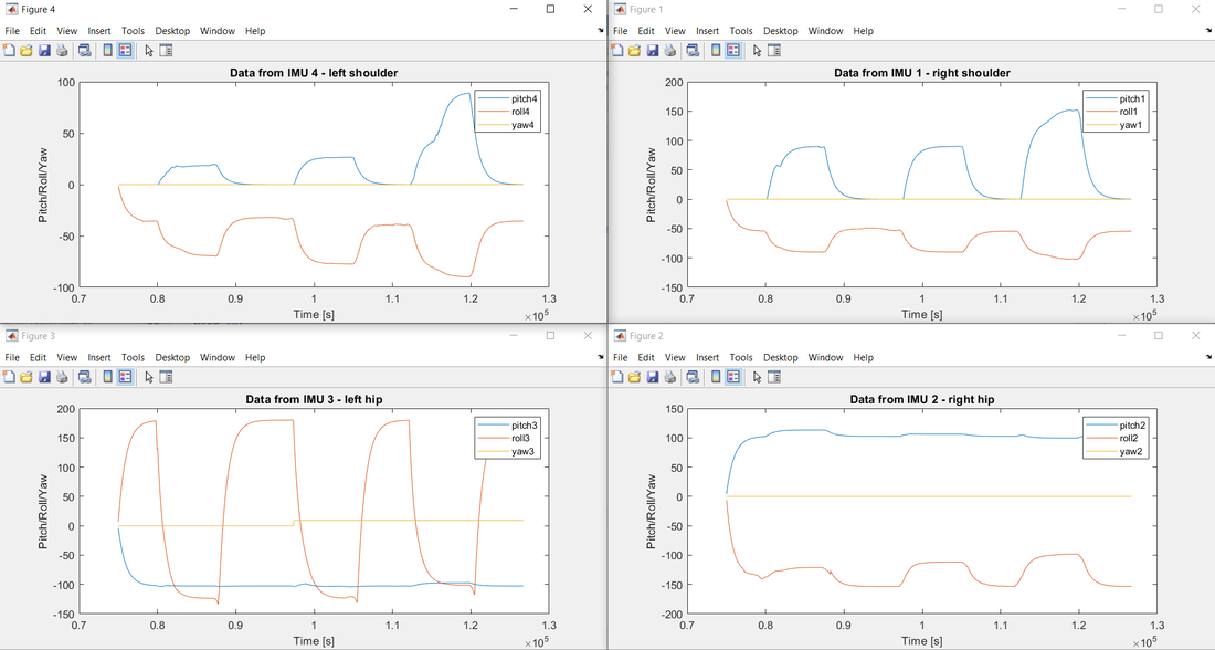 The test was conducted multiple times to obtain the pitch, roll, and yaw values of all the IMUs when the user is in a slouched position. These tests determined the threshold values for this position. The next testing position involved the user dropping one hip and supporting their weight on one side of their body. The results are graphed below: 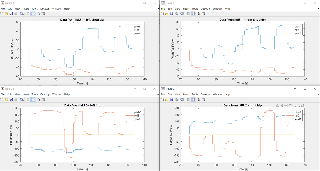 This test was repeated 3 times to obtain the required threshold values for this position. The next testing position involved the user leaning left and right, alternately. The results are graphed below: 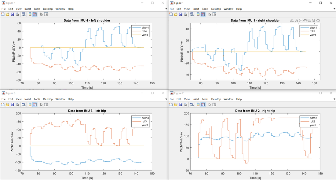 This test was repeated multiple times to obtain the required threshold values. The final testing position involved the user leaning backwards at various levels. The results are graphed below: 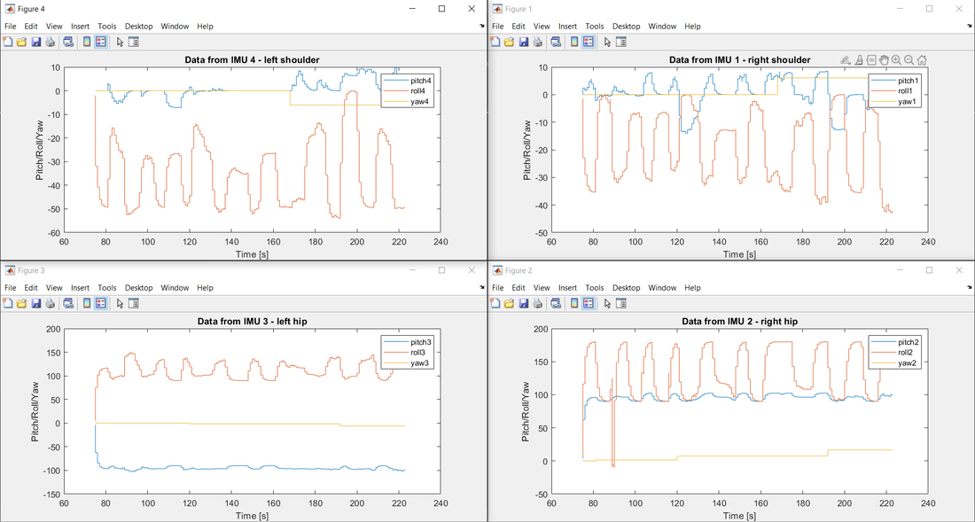 The test provided the threshold values for this position.
The various thresholds were used to define 4 distinct postures. The algorithm uses a voting system to determine which incorrect position the user is currently in, and then buzzes the corresponding motors.
0 Comments
The Bluetooth module is essential for communication between the vest and the mobile app. The module that is being used for this project is the HC-06 Bluetooth module. Once it was delivered, testing was conducted to ensure it worked correctly before being soldered to the other components. An online tutorial was used to reduce the time spent on testing. First, an Arduino Nano was wired to an LED and the Bluetooth module. Then the Arduino was powered on and the Bluetooth module was paired to an Android phone. The tutorial code was uploaded to the Arduino, which required that the TX and RX pins be temporarily disconnected from the Bluetooth module to avoid interference and the app was downloaded to the phone. Finally, the app was used to turn the LED on and off using the Bluetooth connection. After the HC-06 Bluetooth module was tested, a spare HC-05 was tested as well, in case any backup parts are needed in the future. The HC-05 functioned just as well. Now that the Bluetooth module has been confirmed to work, the next steps are to add code to the FlexiVest app and Arduino so that they can establish a connection and transmit data. 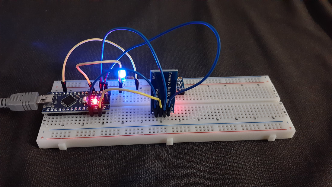 After initializing the separate IMU modules and determining optimal positions for each component, a prototyping wire harness was constructed to connect the components along the back brace. This involved soldering 20 AWG wire to connect the components as per the wiring diagram created during the planning phase. After soldering the IMU modules, Arduino Nano, and I2C Multiplexer, the wire harness was fastened to the back brace using electrical tape in order to allow for fast prototyping and easy adjustment during testing. Next steps are to collect data from the IMUs based on movements and positions recorded from the back brace. Then, flex sensors will be added and vibration motors will be installed to provide feedback to the user.
One important part of FlexiVest is the mobile app that will allow users to view metrics about their posture throughout the day. In order to store the necessary data, a database will be implemented. Since some data needs to be modifiable, such as the calibration data, an easily modifiable database is preferred. Therefore a NoSQL database is appropriate. MongoDB is selected since it is a NoSQL database and because team members have previous experience using this database platform. The data must be accessible from multiple devices and thus the database should be hosted on the cloud. There are several options for doing this, and both Amazon Web Services (AWS) and Google Cloud Platform were considered. A large amount of storage is not necessary, so the free tier options were investigated. Google Cloud Platform was selected for hosting as the free tier doesn't require payment information which is required for AWS. Once a MongoDB cluster was created and deployed, login profiles were created for each team member and the MongoDB Compass GUI was used to verify that multiple team members could access and sync data from the database. Sample IMU data with "pitch," "yaw," and "roll" fields were created for this purpose. 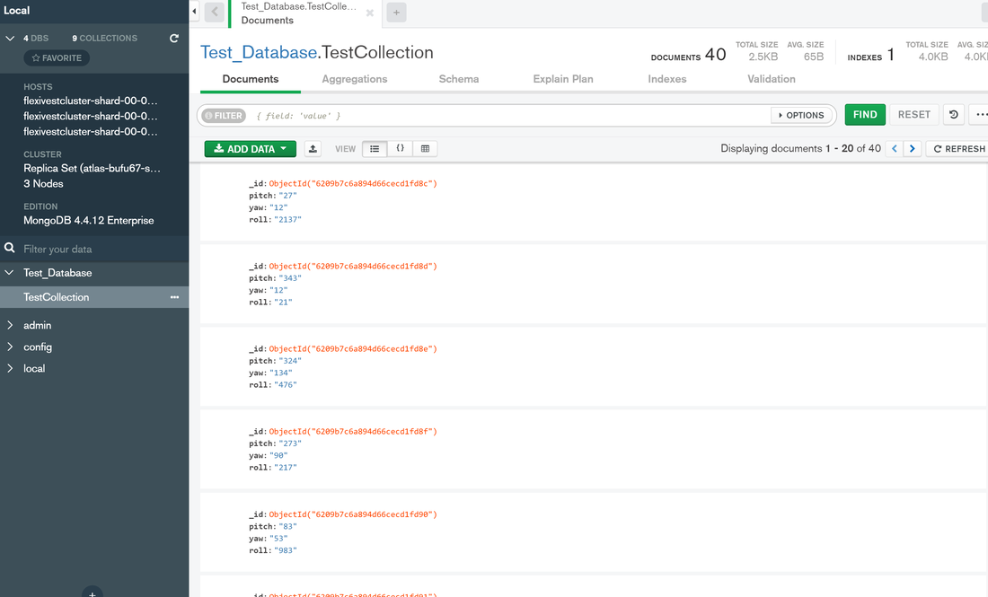 With the database deployed, the next step is to develop an API to send and retrieve data between the app and the database.
A major instrument in collecting information about the posture of users with the FlexiVest are flex sensors. In order to properly place the flex sensors and determine the sensitivity of the flex sensors, initial tests were run to find the output values of the flex sensors at various radii of curvature. The goal was to find a relationship between resistivity and the bending angle of the sensor. A 10 cm flex sensor was used to understand the general behavior of flex sensors and as a potential flex sensor candidate in the final prototype. In the initial design, the following schematic presented the circuit needed for the flex sensor. The schematic shows the input pin of the arduino connected to a voltage divider circuit, with 47 kΩ fixed pull-down resistors.  When the flex sensors were connected to the arduino in this specific way, it was found that the output provided by the sensor was not sensitive enough, so the value of the resistor was dropped to 10 kΩ, so that the output value could be effectively amplified. In order to collect the radius of curvature vs. flex sensor output value, an experiment was designed. An Arduino Uno was connected to the flex sensor as shown in the Schematic presented earlier and a serial monitor tracked the value of the flex sensor output. The flex sensor was then bent along different radius of curvatures, as shown in the animation:  The output of the flex sensor was monitored and recorded over short intervals with Microsoft Excel’s Datastreamer. After the output values over short time intervals were obtained for 9 different radii of curvature, an average output value for each radius was calculated. The following table shows the relationship between the radius of curvature and Output:  These results are a little ambigiuous and do not show the expected linear relationship. Infact, the suggest a weak correlation between the radius of curvature and output. In order to refine this characterization, a new experiment will have to be done which focuses specifically on angle ranges or radius of curvatures that the human spine can contort to. When the range is limited in this way, it will be easier to design specifically for the FlexiVest case and find a necessary relationship.
In order to use four IMU devices from one microcontroller, it is essential to ensure that there is reliable communication between the devices. Our implementation for this project is to use four MPU 6050 IMU devices, located at the waist and shoulders of the back brace. In the initialization process for these components, we must ensure that the Arduino Nano can communicate consistently and reliably with each IMU to collect positional data. Since it is not critical for the devices to read synchronously to the Arduino, they will be called in succession to read data, at relatively close time stamps to simulate a “simultaneous” output. One issue with this implementation is that the Arduino Nano only has one I2C module, and the MPU 6050 IMUs each have two possible I2C addresses. Clearly this is insufficient, since we would need four IMUs, each with its own I2C address, in order to separately communicate with the microcontroller. To solve this issue, an I2C Multiplexer (TCA9548A) was purchased, which holds eight I2C addresses (0x70 through 0x77) and can connect to up to 8 same-address I2C devices. As such, the four IMU modules can be connected to four of the eight possible address ports on the multiplexer, and the Arduino can communicate with each of the IMUs through the multiplexer. A simple initialization test was run to ensure unique and valid data could be obtained from each of the IMUs separately. For the purposes of this proof-of-concept, raw roll, pitch, and yaw values were collected from three separate MPU6050 modules on a breadboard setup. 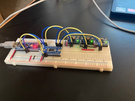 The results of this test were a success and concluded that the Arduino Nano could successfully communicate with multiple IMU devices through an I2C multiplexer.
|
Team FlexiVestDesigning and Implementing the FlexiVest prototypes ArchivesCategories |


 RSS Feed
